Preface
This website contains labs for CSCI 210.
At the top of this page, you’ll find three icons. The left shows or hides the table of contents. The middle one lets you pick a theme for this book (go ahead and pick one you like). The right one lets you search the labs.
Throughout the labs, you’ll find a number of colorful blocks like the example above. Here are a few you’ll encounter in the labs.
Example boxes contain important examples, usually of code that’s similar to the code you will be writing.
Tip or hint boxes contain important information that you’re almost certain to want to use in your implementations.
There are a variety of other boxes, including note, info, and caution. At this point, they have no fixed meaning. This may change.
Lab 1. Introduction to MIPS
Due: Sunday, February 22 at 23:59
Your task is to write a program which takes in a number and stores it in a four-element array at a user-specified index, then prints the contents of the array. You will write this program using the MARS MIPS simulator, which you can download here.
Preliminaries
First, download MARS (there’s a “Download MARS” button at the top of the page).
If you don’t already have a GitHub account, make one. As a student, you can get additional GitHub benefits such as unlimited private repositories here, but you don’t need to for this course. All of your repositories will be private to you and course instructors.
You’ll need Git installed in order to download and submit assignments. On macOS, Git is included with Xcode which can be installed from the App Store. On Linux, Git can be installed using your distribution’s package manager. You can install any of the many other Git tools instead, including GitHub Desktop on macOS and Windows.
Click on the assignment link.
Once you have accepted the assignment, you can clone the repository on your computer by following the instruction and begin working.
Program specification
Read two input values from the keyboard:
- a number to enter in the array; and
- the index of the array where you should store the first number.
Print out each index of the array, and its contents. It should look like this.
  Please enter a number 6
  Which element of the array would you like this to be? 1
  0: 0
  1: 6
  2: 0
  3: 0
Or like this.
  Please enter a number 3
  Which element of the array would you like this to be? 0
  0: 3
  1: 0
  2: 0
  3: 0
You can assume the user will not input any indexes outside of the bounds of the array. You are required to store the user’s value in memory at the specified position, and to load every value in the array from memory into a register to print it out.
Note that you will need to translate between indices, which are word addresses, and values in memory, which are byte addresses.
Make sure to document your programs thoroughly. (This is especially important in assembly language programs, since the code itself is less easily read than high-level language code.) This should include:
- A block of comment lines at the beginning of the source file, giving the name and author of the program and a black-box description of what it does.
- A few comment lines between major sections of the program, describing the contents of each section.
- A comment at the end of most source lines, describing what the instruction on that line does.
Helpful resources
Hints
- You will need to use various system calls to print strings, integers, etc. These are all provided on the list of system calls linked above.
- The
lainstruction loads the address of a label. You can use this to load the addresses of any of the variables in the.datasection of your code. - The
mulinstruction will allow you to multiply a register by a constant. - I have included some strings you may find helpful in the
.datasection. - You do not need to write any loops.
- Your array must be 4-byte aligned. You can use
to get a 4-byte aligned array..align 2 arr: .space 16
Submission
Submit the lab by committing your code and pushing it to your GitHub repository. From the command line, you would enter the commands
$ git commit -m "Finished!" lab01.asm
$ git push
from inside your repository’s directory.
The first command instructs Git to take the changes that you made to
lab01.asm and record those changes on your computer. Usually, when writing
software, you would make multiple commits. This allows you to “easily” go back
to previous versions. (“Easily” is in quotes because nothing with Git is ever
actually easy.)
The second command instructs Git to take all of the changes that you have committed and push them to your repository on GitHub. You can push each time you commit, or you can push after several commits have been made and all commits that haven’t yet been pushed to GitHub will be pushed at that time.
If you don’t push after committing the final version of your code, the graders will not be able to see your changes (because they’ve only been recorded on your local computer).
Rather than use the command line, you can visit the web page for your repository on GitHub and drag and drop the files on the page. I don’t really recommend doing this; it’s better to learn how to use Git properly. But it does work and you’re welcome to do it.
Lab 2. Bitwise Operations
Due: Sunday, March 1 at 23:59
Your task is to write a Rust program that performs bit operations on integers.
Preliminaries
Click on the assignment link.
Once you have accepted the assignment, you can clone the repository on your computer by following the instruction and begin working.
This lab is in Rust. You’ll either need to have the Rust toolchain installed on your computer (I recommend using rustup) or use the lab machines which have Rust installed.
Program specification
In the assignment repository you will find a Rust project named bitops. This
project contains source code for a library src/lib.rs which you will be
editing and a binary src/main.rs which you will not be editing.
Your task is to implement the functions in src/lib.rs. You are only allowed
to use the Rust bit operators, & (and), | (or), ^ (xor), >> (right
shift), and << (left shift). You will not receive credit for the lab if
you use addition, subtraction, division, multiplication, modulo/remainder, or
control flow constructs like if and loops.
You must perform bit operations directly on the integer passed to each
function, and you are not allowed to convert the integer to another format.
In particular, you may not convert the integer to a String. For any method
that asks you to change specific bits, you should assume bits are numbered 31
to 0, with 31 being the most significant bit or highest bit, and 0 being the
least significant bit or lowest bit. All of these methods can (and should) be
implemented with a single line of code.
For example, say I asked you to write a function named set_bit_one that sets bit
one of an integer to one while leaving the rest of the bits unchanged. My code
for that method would look like this:
#![allow(unused)]
fn main() {
fn set_bit_one(x: u32) -> u32 {
    x | 2
}
}
Make sure you understand why this is ORing x with 2.
It may be helpful to know that you can specify the value of an integer in
hexadecimal by prepending it with 0x, e.g., let x = 0xBADBEEF;. You can
also specify the value of an integer in octal by prepending it with 0o or in
binary by prepending it with 0b.
Fun fact: Many programming languages—such as C and Java—use a leading 0
to indicate that a number is in octal. For example, in C or Java 0755 is how
the integer 493 would be written in octal. In Rust, we would write 0o755.
The bitops binary whose source code is in src/main.rs takes input in the
form of command line arguments. Each command line argument is parsed as an
integer and passed to each of the functions you have to implement and the
results are printed to stdout. The inputs can be specified in decimal, octal,
hexadecimal, binary, or as an IPv4 “dotted quad” address like
132.162.201.24. See the examples below.
You will need to implement the following functions.
-
fn is_odd(x: i32) -> i32: This method returns 1 ifxis odd, and 0 if it is even. It returns 0 on 6, and 1 on 5. -
fn is_negative(x: i32) -> i32: This method returns 0 if x is positive, and 1 if x is negative. It returns 0 on 4, and 1 on -3. -
fn div_by_4(x: u32) -> u32: This methods performs unsigned integer division by 4. It returns 1 on 6, 3 on 13, and 0 on 3. -
fn nearest_odd(x: i32) -> i32: This method rounds up the number to the nearest odd number. It returns 7 on 6, 5 on 5, and -3 on -4. -
fn flip_parity(x: i32) -> i32: This method adds 1 to even numbers, and subtracts one from odd numbers. It returns 7 on 6, 4 on 5, and -4 on -3. -
fn routing_prefix(addr: u32) -> u32: IPv4 network addresses are stored as 32 bit integers. Each address is divided into two parts: the routing address and the host address. The routing address specifies the network the computer is on (for example, Oberlin’s network). The host address identifies a specific computer on that network. A subnet mask is applied to an IPv4 address to zero out bits corresponding to the host address, leaving just the routing prefix.Your task is to write a function that returns the routing addresses for a network with 256 host addresses: these routing addresses will consist of the 24 highest order bits of the address, with the last 8 bits of the address set to 0. If you code this function correctly, the IP form of your result should look like
x.x.x.0. -
fn make_readable(perms: u32) -> u32: The chmod, or change mode, command in Unix is used to change access permissions. It accepts user permission flags as a 3 digit octal number, where the first digit corresponds to the User permissions, the second digit corresponds to the Group permissions, and the third digit corresponds to the Other permissions. Each octal digit is three bits. For chmod, we set the most significant bit of the digit to 1 to give read permission, the middle bit to 1 to give write permission, and the least significant bit to 1 to give execute permission. For this function, take in a number that represents a set of permissions, and set all the read permission bits to 1. All other permission bits should remain unchanged. Good values for testing are 0, 64 (0o100in octal, i.e. execute for user and no permissions for anyone else), and 146 (0o222in octal, or only write permissions set for everyone).
Testing
For each function that you implement, write a unit test containing at least 3
assertions. Your tests should appear in the test module in src/lib.rs. A
test function for is_odd is provided for you to use as a template for other
tests. You don’t need to add additional tests for is_odd, but you may if you
wish.
To run the tests, you can run
$ cargo test --lib
in the terminal.
Examples
Here are some sample outputs when running bitops with different arguments.
$ cargo run --quiet -- 0o640
is_odd(416) = 0
is_negative(416) = 0
div_by_4(416) = 104
nearest_odd(416) = 417
flip_parity(416) = 417
routing_address(416 /* 0.0.1.160 */) = 256 /* 0.0.1.0 */
make_readable(0o640) = 0o644

$ cargo run --quiet -- -87
is_odd(-87) = 1
is_negative(-87) = 1
div_by_4(4294967209) = 1073741802
nearest_odd(-87) = -87
flip_parity(-87) = -88
routing_address(4294967209 /* 255.255.255.169 */) = 4294967040 /* 255.255.255.0 */
make_readable(0o37777777651) = 0o37777777655

$ cargo run --quiet -- 132.162.201.24
is_odd(-2069706472) = 0
is_negative(-2069706472) = 1
div_by_4(2225260824) = 556315206
nearest_odd(-2069706472) = -2069706471
flip_parity(-2069706472) = -2069706471
routing_address(2225260824 /* 132.162.201.24 */) = 2225260800 /* 132.162.201.0 */
make_readable(0o20450544430) = 0o20450544474
These examples make good test cases but don’t necessarily cover every case you may wish to test.
Submission
Submit the lab by committing your code and pushing it to your GitHub repository.
Lab 3. MIPS Fibs
Due: Sunday, March 8 at 23:59
Your task is to write a program which computes an initial portion of a generalized Fibonacci sequence and prints it out. You will write this program in MIPS using the MARS simulator.
Preliminaries
Click on the assignment link.
Once you have accepted the assignment, you can clone the repository on your computer by following the instruction and begin working.
Program specification
No starter code is provided this time. Create a file in MARS called lab3.asm
and create your program there. You may wish to look at your code for Lab
1 for reference.
Input
Read three input values from the keyboard:
- the first number in the sequence,
- the second number in the sequence, and
- the number of elements of the sequence.
Each element of the sequence (beyond the first two) is equal to the sum of the previous two. For example, if the user inputs 3, 1, and 10, then your program should generate the sequence 3, 1, 4, 5, 9, 14, 23, 37, 60, 97.
Output
For each element of the sequence that you generate, display
- the number in decimal notation (using system call 1),
- the number in hexadecimal, and
- the number of 1-bits in the binary representation of the number.
For the example above, you would display the following.
3 0x00000003 2
1 0x00000001 1
4 0x00000004 1
5 0x00000005 2
9 0x00000009 2
14 0x0000000E 3
23 0x00000017 4
37 0x00000025 3
60 0x0000003C 4
97 0x00000061 3
The hex version can be displayed using system call 34.
Implementation
To get full credit for this assignment, you will need to create a function to count the number of ones in a number. You should use proper calling conventions as discussed in class. You will also need to use a loop to generate the generalized Fibonacci numbers.
You will not need to use either arrays or recursion for this problem. You are required to write a separate function which counts the number of ones in a number. (Hint: Think about using bit operations to isolate each bit in the number, and add them together.)
Make sure to document your programs thoroughly. (This is especially important in assembly language programs, since the code itself is less easily read than high-level language code.) This should include:
- A block of comment lines at the beginning of the source file, giving the name and author of the program and a black-box description of what it does.
- A few comment lines between major sections of the program, describing the contents of each section.
- A comment at the end of most source lines, describing what the instruction on that line does.
- Write a program that does this in a high-level language and then translate it to MIPS. It will be a lot easier to solve this problem if you figure out the logic first and write the assembly for it second.
- Syscall 35 will print an integer in binary.
- To count the ones in a number, think about using bit operations to isolate each bit of the number and then add the bits together. A loop and bit shifting instructions will be helpful here.
- Printing the string
\t(the tab character) between each number will give you the nice even spacing shown in the example. Likewise, printing the string\nwill give you a newline.
Helpful resources
Submission
Submit the lab by committing your code and pushing it to your GitHub repository.
Lab 4. MIPS Array
Due: Sunday, March 15 at 23:59
Your task is to write a program to read a list of (x,y) pairs representing
points in the xy-plane and print them in ascending order, according to their
distance from the origin. You will write this program in MIPS using the MARS
simulator
Preliminaries
Click on the assignment link.
Once you have accepted the assignment, you can clone the repository on your computer by following the instruction and begin working.
Program specification
No starter code is provided this time. Create a file in MARS called lab4.asm
and create your program there. You may wish to look at your code for Lab
3 for reference.
Input
The first line of input is an integer (with ) representing the number of points in the list. This is followed by additional lines of input containing the coordinates of the points to be sorted. For example, the list would be input as:
4
3
4
4
2
0
-5
1
3
You can read the values using system call 5 (read integer). (System call 5 requires that only one integer appear on each line.)
The input should be stored in an array. You can view the storage conceptually as a series of pairs, as shown below.
3  4
4  2
0 -5
1  3
Output
The output of the program will consist of lines, each containing the x- and y-coordinates of one point in the sorted list. For example, the output from the list of 4 points shown above would be the following.
1    3
4    2
0    -5
3    4
Implementation
You will need to
- allocate space for the data on the heap using
sbrk; - decide how to map the data to the space you allocate; and
- determine how to address the x- and y-coordinates of each point.
Once you have read in all the data, you need to sort it in increasing order according to the value of ; that is, the square of the distance from the point to the origin. If two points in your list are the same distance from the origin, they should be sorted in lexicographic order; that is, first in increasing order according to the x-coordinate, and if the x-coordinates are the same, then according to the y-coordinate. If the same point appears more than once in the input, it should appear with the same multiplicity in the output. For example, the correct ordering of the points , , , , would be , , , , .
You may use any sort method that you choose. I would recommend using something simple like insertion sort. Keep in mind that when you swap two points in your list, you must swap both their x- and y-coordinates.
You may assume that overflow will not occur as a result of computing .
For full points, you must structure your solution to use functions. See the next section for the required list of functions. Functions must be proper functions with arguments passed in the argument registers, results returned in the return registers, caller-saved registers that are used must be saved before use and restored before returning.
Plan for developing the program
First, write and debug a program that will read and the list of points, store each point in the array, and print it in the desired format.
After that, go back and add the sort operation. Make sure to test!
You will need to write the following functions.
- (5 pts) A
mainfunction that reads the number of points from the user, allocates enough space to hold the points (each point is two integers) and then calls three functions,read_points,sort_points, andprint_points. It ends by calling the exit system call. - (5 pts) A
read_pointsfunction that takes a pointer to the array of points and the number of points. In a loop, it reads the x- and y-coordinates for each point and stores them in the array. - (9 pts) A
sort_pointsfunction that takes a pointer to the array of points and the number of points. I used one of the sorting algorithms you learned about in 150 rather than something faster like Quicksort or Mergesort. Thesort_pointsfunction needs to determine if one point is “smaller” than another. To that end,sort_pointscalls apoint_less_thanfunction whenever two points need to be compared. Many sorting algorithms are built on the idea of swapping two elements so you will write aswapfunction that swaps two elements. - (8 pts)
point_less_thantakes two pointers as arguments. The first pointer points to the first point and the second to the second point. Since each point is just two consecutive integers, ifpwere a pointer to a point, then (in C),p[0]is the x-coordinate andp[1]is the y-coordinate. In MIPS, since$a0will be the argument register holding the first pointer, we can access the x- and y-coordinates as follows.lw $t0, 0($a0) # load the x-coordinate of the first point into $t0 lw $t1, 4($a0) # load the y-coordinate of the first point into $t1point_less_thanreturns 1 if its first argument is less than its second; otherwise, it returns 0. - (8 pts) Like
point_less_than,swaptakes two pointers to points as arguments. It loads the four integers (two for each point), and then stores them in the appropriate location for the other point. - (5 pts) A
print_pointsfunction which prints the points in a loop.
Each of these 6 functions must be a proper function meaning arguments are
passed in $a0 through $a3 and the return value (if any) is in $v0.
Proper stack manipulation must be performed (reserving space on the sack for
registers, including $ra in the prologue and cleaning it up in the
epilogue).
Writing proper functions
You may initially find writing proper functions to be a hassle, but doing so will make your code vastly easier to read and reason about. And it’s required to get full points.
I recommend reviewing the slides for “Procedures” and “The stack” on the
course website for details on how to correctly construct a stack frame.
Briefly, every non-leaf function needs to allocate a stack frame that contains
space for local variables and temporaries, saved registers (like $ra and
$s0), and at least space for 4 words of “argument build area” (which the called function can use to save the argument registers). Stack frames should be a multiple of 8-bytes in size. See the below figure from the MIPS ABI.
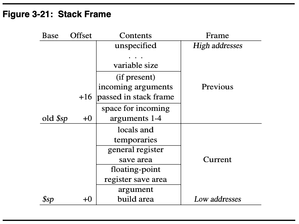
When figuring out the size of the stack frame for a function, count how many
registers you need to save (which will be at least one for $ra), add 4 for the “argument build area” and round up to a multiple of 2. This gives you how many words you need to allocate for the stack frame. Multiplying by 4 gets you the number of bytes to decrement the stack pointer. For example, a non-leaf function which only needs to preserve $ra requires a stack frame of size bytes.
Finally, the MARS simulator initializes the stack frame to a multiple of 4, but not a multiple of 8. A neat trick to round a positive number (like an address) down to the nearest multiple of a given power of 2 is to AND the number with the negative of the power of two. In this case, we want to round $sp down to the nearest multiple of 8 so we can use
li    $t0, -8
and   $sp, $sp, $t0
as the first two instructions in main to get an 8-byte aligned stack
pointer. After these two instructions, you’ll want to decrement the stack
pointer to allocate a stack frame for main.
Helpful resources
Submission
Submit the lab by committing your code and pushing it to your GitHub repository.
Lab 5. 7-segment display
Due: Sunday, March 29 at 23:59
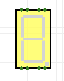
In this assignment, you will design a combinational logic circuit which will control a 7-segment LED display, which looks like this.
Preliminaries
We will be using the CircuitVerse website to complete this assignment. You should have received an email inviting you to the “CSCI 210 Spring 2026” group on CircuitVerse. If you did not, please use this link to join the group. To start the assignment, click on your name on the upper righthand side of the website. Go to “My Groups” and then select the group for this class and you should see “Lab 5” under assignments. Click the “Start Working” button to start the assignment. After you click “Start Working” you can click “Launch Simulator” to start creating the assignment.
You can find more details on how to use the CircuitVerse website here.
4-16 Decoder
You’re going to use a 4-16 decoder in order to implement the 7-segment display controller. As a subcircuit, implement a 4-16 decoder. It should have 4 input lines representing a number from 0 to 15 and it should have 16 output lines. At any given moment, exactly one output line must be 1 and the other 15 must be 0.
7-Segment Display Controller
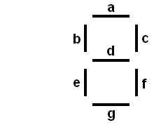
The input to circuit is a set of 4 signals a3, a2, a1, a0 representing the digits of a 4-bit binary number. The output is a set of the seven signals a, b, c, d, e, f, and g used to drive the seven segments of the LED display. When implemented correctly, your circuit will display value of the input as a hexadecimal digit on the 7 segment display. Below is the display with each segment labeled.
Your display controller should pass its 4 inputs to the 4-16 decoder you constructed and the output of the decoder should be used to drive the seven LED signals.
Each of the LED signals can be represented as a simple boolean function of the
16 decoder outputs. For example, if the input is 0101, the output of the
decoder should be a single 1 which turns on segments a, b, d, f, and g, while
c and e are off, forming the digit “5” on the display.
You should implement all 16 hexadecimal digits, 0, 1, 2, 3, 4, 5,
6, 7, 8, 9, A, b, C, d, E, and F. (Note that b and d
are lower case to distinguish them from 8 and 0.)
Implementation plan
You should use the following plan for implementing this lab.
- Draw out all the numbers on graph paper first.
- For each of the segments a–g, write down which numbers correspond to that segment.
- Build a 4-bit decoder as a subcircuit. You MUST have your decoder as a subcircuit in order to receive full credit for this lab. Documentation for how to create a subcircuit is here.
- For each segment, create one or more OR gates (as needed), add the appropriate outputs from the decoder to the OR gate.
- Keep wires straight or right-angle turns. Pick the order the decoder outputs will go into the OR gates so as to minimize wire crossing.
- If inadvertent connections are made, undo, don’t try to fix it.
Performing step 2 before step 4 is critical. You don’t want to be trying to wire this up while figuring out which decoder outputs you need to OR.
Submission
Make sure to select the “save online” button to save your project. This will make your project available to us for grading.
Lab 6. Adder/Subtracter
Due: Sunday, April 5 at 23:59
In this lab, you will build an eight-bit adder/subtracter.
Preliminaries
We will be using the CircuitVerse website to complete this assignment. To start the assignment, click on your name on the upper righthand side of the website. Go to “My Groups” and then select the group for this class and you should see “Lab 6” under assignments. Click the “Start Working” button to start the assignment. After you click “Start Working” you can click “Launch Simulator” to start creating the assignment.
You can find more details on how to use the CircuitVerse website here.
Adder/Subtracter
Your adder/subtractor must take in two 8
bit numbers, a and b, and one select value, s, and have an 8 bit output, c. If s
is zero, your adder should output a + b. If s is one, your adder should output
a - b. For some examples, look at the table below.
| a | b | s | c |
|---|---|---|---|
| 00001100 | 00001000 | 0 | 00010100 |
| 00001100 | 00001000 | 1 | 00000100 |
| 01101000 | 01010000 | 0 | 10111000 |
| 01101000 | 01010000 | 1 | 00011000 |
Note that in the third example, we get the wrong answer because of overflow—just like many modern programming languages, we are going to ignore this.
Implementation plan
You are required to build this adder/subtracter using only with basic logic gates (i.e., AND, OR, NOT, NOR, NAND and XOR). You are not allowed to use the CircuitVerse adder. You should take the following steps.
- Build a one-bit half-adder as a subcircuit;
- Build a one-bit full-adder out of half-adders, also as a subcircuit; and
- Build an eight-bit adder/subtracter out of eight one-bit full-adders.
You are required to have a separate half-adder and full-adder subcircuit to get full credit for the lab.
Submission
Make sure to select the “save online” button to save your project. This will make your project available to us for grading.
Lab 7. Four-bit Counter
Due: Sunday, April 12 at 23:59
In this lab, you will build an four-bit counter out of J-K flip-flops. To build the J-K flip-flops, you’re going to build a clocked S-R latch.
Preliminaries
We will be using the CircuitVerse website to complete this assignment. To start the assignment, click on your name on the upper righthand side of the website. Go to “My Groups” and then select the group for this class and you should see “Lab 7” under assignments. Click the “Start Working” button to start the assignment. After you click “Start Working” you can click “Launch Simulator” to start creating the assignment.
You can find more details on how to use the CircuitVerse website here.
Clocked S-R latch
You should first build a clocked S-R Latch as a subcircuit. Lectures 18 and 19, as well as Appendix B.8 of the textbook should be helpful to you here. The S-R latch must be a subcircuit to get full credit for the lab.
Your subcircuit should take in inputs S, R and C (for clock), and have outputs Q and Q. When C is 1, the outputs Q and Q are controlled by S and R. When C is 0, the outputs should not change regardless of the values of S and R. (Note that for this subcircuit, you should make the clock an input value, and not actually hook up the clock to the circuit.)
The S-R latch must be a subcircuit to get full credit for the lab.
J-K flip-flop
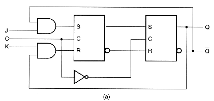
Next you will build a J-K flip-flop out of two clocked S-R latches. Your subcircuit inputs should be J, K and C (for clock again), and your output should be Q. The J-K flip-flop must be a subcircuit in order to get full credit for the lab. Below is a circuit diagram for a J-K flip-flop. (Please note that the circles on the Q output of this diagram are just to indicate that the output is the inverse of the Q output; they don’t mean that Q is being inverted to be the same as Q!)
Counter
Your main circuit is a four-bit counter which you will build out of four J-K flip-flops.
This circuit should not require any input from the user/viewer of the circuit; you should use the clock as input, and it should automatically make your counter increase by one for every clock cycle. Your output should be a binary number displaying the current count. You can either display this as 4 individual 1-bit outputs, or 1 four-bit output. Your counter should count through 0000, 0001, 0010, 0011, …, 1110, 1111 and then start over at 0000.
Let’s start by considering a 1-bit counter. Every clock cycle, the output should alternate between 0 and 1. See the timing diagram below. Notice how output alternates between 0 and 1 and it stays at each of those for an entire clock period (the interval between the blue lines).

Look at Problem Set 8. There is a particular configuration of inputs to a J-K flip-flop that causes the output to “toggle” between 0 and 1 every time its clock input, C, changes from 1 to 0. Using a single J-K flip-flop, you can construct a 1-bit counter.
Next, let’s build a 2-bit counter. This should count as 00, 01, 10, 11, 00. Notice that the least-significant bit, , toggles on every clock cycle but only toggles when changes from a 1 to a 0, not when the clock changes from a 1 to a 0. In the image below, the blue vertical lines correspond to the counter values 00, 01, 10, 10, 11, 00, from left to right.

To get a 2-bit counter, we just need two J-K flip-flops with appropriate J and K values and with the clock input of the second J-K flip-flop being the output from the first flip-flop.
Similarly, we can build a 3-bit counter by adding another flip-flop. Look at the timing diagram below. When does toggle?

We can continue this process to get a 4-bit counter.

Implementation plan
You are required to build this counter using only with basic logic gates (i.e., AND, OR, NOT, NOR, NAND and XOR). You are not allowed to use the CircuitVerse latches and flip-flops. You should take the following steps.
- Build an S-R latch as a subcircuit;
- Build a J-K flip-flop as a subcircuit; and
- Build a four-bit counter out of four J-K flip-flops.
You are required to have a separate S-R latch and J-K flip-flop subcircuits to get full credit for the lab. You must build your own J-K flip-flops and S-R latches. Using the CircuitVerse latches or flip-flops will result in a failing grade for this lab.
Submission
Make sure to select the “save online” button to save your project. This will make your project available to us for grading.
Lab 8. Floating Point
Due: Sunday, April 26 at 23:59
In this lab, you will implement part of the IEEE 754 Standard for Floating-Point Arithmetic. In particular, you will implement half-precision (16-bit) floating point addition.
This lab has opportunities for extra credit.
In addition to the implementation, there are questions to answer.
Preliminaries
You may work on this lab in groups of up to two people.
Click on the assignment link.
Once you have accepted the assignment, you can clone the repository on your computer by following the instruction and begin working. If you’re working with a partner, the first person to accept the repository will create the team name. The second person will select which team to join. DO NOT JOIN THE WRONG TEAM
Background
Half-precision floating point numbers are similar to the 32-bit single-precision and 64-bit double precision floating point numbers we talked about in class. Click on the link in the previous sentence to read more about half-precision floating point numbers.
Just like single- and double-precision floating point numbers, half-precision floating point numbers are represented with three fields, one sign bit, five bits of biased exponent, and 10 fraction bits. The half-precision format represents 5 categories of numbers based on the values stored in the exponent and fraction fields. These categories are described in the table below with being the value of the sign bit and being the value of the fraction field.
| Category | Exponent | Fraction | Represented number |
|---|---|---|---|
| Normal | anything | ||
| Subnormal | nonzero | ||
| Zero | |||
| Infinity | |||
| NaN | nonzero | Not a Number |
As you can see from the table above, normal numbers are stored with an
exponent bias of 15. For example, the number
so it would be represented with
, , and yielding the binary
representation 1 10100 0010101000. Click
here to play around with other values.
The smallest, positive, normal number has representation 0 00001 0000000000
which corresponds to the value . Smaller positive values are
represented as subnormal numbers. As you can see from the table
above, these are represented with an exponent field of 0 and nonzero fraction
field and the number they represent does not have a “hidden bit.” Instead,
the entire significand is stored in the fraction field which is why the
“Represented number” column shows whereas the normal
numbers have .
Program Specification
In the assignment repo, you’ll find a Rust project containing a single source
file, src/lib.rs and several testing files in the tests directory.
Inside src/lib.rs, you’ll find a Rust struct named F16 which contains a
single u16 field. Each F16 holds a single half-precision floating point
value as a 16-bit unsigned integer.
To create an F16 with a given bit representation, you can write
F16(representation). For exmaple, to create an F16 that represents ,
write, F16(0b1_00000_0000000000) (Rust lets you separate your numbers using
_ as in that example, You could equivalently write this as
F16(0b1000000000000000). Of course, you could specify it with hex
F16(0x8000).)
Several functions are provided for you, F16::from_f32() and F16::to_f32()
convert from or to f32, Rust’s single-precision floating point number type.
You must not use these functions in your code. They are provided to support
testing and printing. You may print an x: F16 normally, println!("{x}")
which converts x to an f32 and prints that, or you may print it using the
“debug” representation, println!("{x:?}") which will print in scientific
(binary) notation.
You must use bit masking and shifting to manipulate bits. In particular, you are not allowed to convert your integers to strings.
Number representation (13 points)
Your first task is to implement all of the functions in src/lib.rs that
contain todo!("Implement me"). These functions are described briefly below
with more comments appears in src/lib.rs.
-
(3 pts)
fn from_parts(negative: bool, exponent: u16, fraction: u16) -> Selfconstructs anF16from the three fields: sign, exponent, and fraction. You should construct the 16-bit representation of the number and return it as anF16. For normal numbers, theexponentargument will already be biased. -
(3 pts)
fn to_parts(self) -> (bool, u16, u16)returns a triple containing the sign bit (as abool), the (biased) exponent, and the fraction bits. This is a counterpart toF16::from_parts()described above.
You should start by implementing these functions and all of the other
functions you write will use one or both functions. After you write these, you
should run the tests to make sure the test_round_trip_through_parts test
passes successfully. (See below for how to run the tests.)
- (1 pt)
fn is_zero(self) -> boolreturnstrueifselfrepresents . - (1 pt)
fn is_sign_positive(self) -> boolreturnstrueifself’s sign bit is 1. - (1 pt)
fn is_sign_negative(self) -> boolreturnstrueifself’s sign bit is 0. - (1 pt)
fn is_infinite(self) -> boolreturnstrueifselfrepresents . - (1 pt)
fn is_nan(self) -> boolreturnstrueifselfrepresentsNaN. - (1 pt)
fn is_normal(self) -> boolreturnstrueifselfrepresents a normal number. - (1 pt)
fn is_subnormal(self) -> boolreturnstrueifselfrepresents a subnormal number.
For each of the preceding functions, you should use self.to_parts() to
determine if the function should return true or false.
After you implement these functions, all of the tests in tests/representation.rs
should pass. (See below for how to run the tests.)
Once all of the tests in tests/representation.rs pass, you can move on to
implementing floating point addition. The first part, described below, is
required. The remaining implementation parts, described on the next page, are
optional and worth extra credit.
Implementing addition for zero and normal numbers (17 points)
The fn add(self, rhs: Self) -> Self::Output function takes in two F16,
self and rhs (right-hand-side) which corresponds to the arguments to +
in self + rhs. For ease of reference, the starter code assigns these values
to variables x and y and this description will refer to x and y. The
add function needs to return an F16 that corresponds to the sum of x and
y.
Remember, you are not allowed to convert x and y to f32 and add them
that way. You must implement all of the floating point addition using integer
operations only.
For this required portion, you only have to support adding normal floating point numbers or zeros (positive or negative). This will only be tested by adding normal numbers (or 0) together when the result will be a normal number (or 0).
You should implement the following algorithm.
- If either
xoryis 0 (you should use youris_zero()function), return the other value. - Otherwise,
xandyare both normal numbers which should be added together and the result will be a normal number or zero- Use
x.to_parts()andy.to_parts()to get the 3 fields of each number and unbias the exponents. - Construct the significands for
xandyby ORing theHIDDEN_BIT(a constant provided for you) with the corresponding fraction fields. - Shift the significand of whichever of
xoryhas the smaller exponent to the right by the difference of the two exponents. At this point, we have two denormalized numbers which have the same (larger) exponent. - Give the significands the sign of their corresponding floating point
value. I.e., if
xis negative, then makex’s significand negative to perform the addition. Similarly fory. The result of this addition is the significand of the final result (including its sign). - If the result’s significand is negative, remember this fact and make it positive.
- If the result’s significand is zero, return .
- Otherwise, normalize the result by shifting the significand left or
right as required such that there is a 1 in the position of the
HIDDEN_BITand only 0s in the more significant bits. Remember to update the exponent when you shift. - Return the resulting
F16viaF16::from_parts(), passing the sign flag, the exponent (after biasing), and the fraction bits (which you get from masking off the hidden bit using a bit operation).
- Use
Let’s add and . After extracting the fields, unbiasing
the exponents, and ORing the HIDDEN_BIT, we have
x_sign = false
x_exp = 5
x_sig = 0b00000100_00110000

y_sign = true
y_exp = -3
y_sig = 0b00000100_00000000
Since y_exp < x_exp, we shift y_sig right by giving
x_sign = false
x_exp = 5
x_sig = 0b00000100_00110000

y_sign = true
y_exp = 5 (note that this was incremented by 8 because we shifted right by 8)
y_sig = 0b00000000_00000100
Next, we add x_sig and -y_sig (it’s negative because y_sign = true) giving
z_exp = 5
z_sig = 0b00000100_00101100
Since z_sig > 0, we set z_sign = false and leave z_sig alone.
Next, we need to shift z_sig left or right until it has a 1 in the position
of the HIDDEN_BIT and 0s in the more significant bits. In this case, we
lucked out and z_sig already satisfies that. Therefore, the final result is
0b0_10100_0000101100.
Let’s add and .
x_sign = true
x_exp = 3
x_sig = 0b00000110_01101000

y_sign = false
y_exp = 3
y_sig = 0b00000110_01100000
Since x_exp = y_exp, we don’t need to shift either.
Next, we add -x_sig and y_sig giving
z_exp = 3
z_sig = 0b11111111_11111000
Since z_sig < 0, we set
z_sign = true
z_exp = 3
z_sig = 0b00000000_00001000
Now we need to shift z_sig left by 7 to put the leading 1 in the correct position.
z_sign = true
z_exp = -4
z_sig = 0b00000100_00000000
Therefore, the final result is 0b1_01011_0000000000.
Once you finish this part, all of the tests in tests/add.rs should pass. See
below for how to run the tests.
Questions (10 points)
Create a README.md with both partner’s names and answer the following questions.
-
(1 pt) We saw in class that single-precision floating point numbers can exactly represent all integers in the range but no larger range. Meaning that is not representable as a single-precision floating point number. Try that out for yourself here. Double-recision floating point numbers can exactly represent all integers in the range but no larger range. (Note that this doesn’t mean that larger integers aren’t representable. For example, is representable in single-precision floating point even though is not.)
What is the range of integers that are all exactly representable in half-precision floating point? (There are several ways to answer this question. One way is to use your
F16implementation. Start withx = 1.0and then add1.0repeatedly toxuntil the value ofxstop changing. One way is to play with float.exposed. -
(1 pt) Somewhat confusingly, there’s a different 16-bit floating point format: bfloat16. It consists of 1 sign bit, 8 exponent bits, and 7 fraction bits. This stands in contrast to the half-precision floating point format (sometimes called binary16) that you implemented. What is the range of integers that are all exactly representable in
bfloat16? -
(3 pts) Generalize your answers to questions 1 and 2 as follows. Given a floating point format with 1 sign bit, exponent bits, and fraction bits, what is the range of integers that are all exactly representable in this format.
-
(1 pt) A common programmer mistake is to use floating point numbers to represent currency. E.g., a novice programmer might represent $10.25 as the floating point number . To show why this is a bad idea, consider starting with a balance of $0.00 and then adding some fixed number of cents like $0.25 one hundred times. The balance will be that number of dollars, $25.00 in the case of a 25¢ increment.
Select an increment in cents (i.e., in the range ) and show that adding it to an initial balance of $0.00 does not give the correct number of dollars when the balance and increment are represented as single precision floating point numbers (
f32). (You may find this Rust playground helpful.) -
(2 pts) Explain why the value you selected in question 4 led to this result with single-precision floating point numbers. Would moving to double-precision floating point numbers solve this problem? If yes, explain how it solves it. If no, explain why it doesn’t solve it.
-
(2 pts) Give an alternative representation of currency one could use that would not suffer from the problem illustrated in question 4. You may assume that you don’t need to represent fractional cents. (E.g., $10.25 is needs to be representable but $10.123 does not.)
Add the README.md to your repository, commit, and push it.
At this point, you should have completed the required implementation and answered all the questions. Congratulations, you’ve completed the lab! Now go take a look at the optional implementation tasks.
Tests
Tests have been provided for your convenience in the tests directory. By
default, running cargo test will run all of the (non-ignored) test functions
found in the files in this directory. We can run tests in specific files by
cargo test --test <test-file-name>.
$ cargo test --test representation
    Finished `test` profile [unoptimized + debuginfo] target(s) in 0.00s
     Running tests/representation.rs (target/debug/deps/representation-790de78c03535650)

running 12 tests
test test_is_infinite ... ok
test test_is_nan ... ok
test test_is_normal ... ok
test test_is_sign_negative ... ok
test test_is_sign_positive ... ok
test test_is_subnormal ... ok
test test_is_zero ... ok
test test_to_f32 ... ok
test test_zero ... ok
test test_round_trip_through_parts ... ok
test test_all_to_f32 ... ok
test test_round_trip_through_f32 ... ok

test result: ok. 12 passed; 0 failed; 0 ignored; 0 measured; 0 filtered out; finished in 0.00s
We can also run a specific test in the file by supplying the name of the test itself.
$ cargo test --test add test_add_zero
    Finished `test` profile [unoptimized + debuginfo] target(s) in 0.00s
     Running tests/add.rs (target/debug/deps/add-05adf8e33ec38607)

running 1 test
test test_add_zero ... ok

test result: ok. 1 passed; 0 failed; 0 ignored; 0 measured; 1 filtered out; finished in 0.00s
The optional parts have more complicated testing requirements. Tests for the optional parts are ignored by default and you’ll have to follow the instructions on the next page to run them.
Hints
-
When implementing
add, you’ll need to shift the significand of the number with the smaller magnitude so that the two numbers have the same exponent. However, if the number of bits you need to shift by is greater than or equal to the number of bits in the datatype (16 for au16, 32 for au32), then you need to set the result to 0 explicitly. If you don’t, you’ll get a panic with a message similar to “attempt to shift right with overflow.” -
When normalizing significands, it’s easy to figure out how far left or right you need to shift the significand by computing the number of leading zeros in the significand. To that end, you can use the
u16::leading_zeros()method. If you’re using a 16-bit type for the significand, then there should be leading zeros. If you’re using a 32-bit type, then there should be leading zeros.
Submission
Submit the lab by committing your code and pushing it to your GitHub repository.
Lab 8. Optional parts
Everything in this file is optional and worth extra credit, up to 10 points. Earlier optional parts must be completed in order to receive credit for later optional parts. There is no partial credit for any of the extra credit parts. Make sure you’ve completed everything else before attempting these.
Up to 10 points of extra credit may be earned.
Handling signed zeros and NaN (1 pt)
In this part, you’ll add support for adding NaN as well as handling signed
zeros in your add() function.
When either of the arguments to add() is NaN, return NaN. There are many
different NaN values. For this part, it won’t matter which one you return.
For the final optional part, we’ll revisit this and return the “correct” NaN.
The description in the required part of the lab said that if one of the
arguments to add() is zero to return the other argument. That isn’t quite
correct if both x and y are zero. In that case, we need to return a zero
but or ? The rule here is simple: if both zeros have the same
sign, return a zero with that sign. If they have opposite signs, then return
positive zero. Finally, adding (finite) values and returns positive
zero.
We can express these two rules in the following equations.
You can test your code by running cargo test --test nanzero -- --ignored
(note all the -- there, they’re all required).
$ cargo test --test nanzero -- --ignored
    Finished `test` profile [unoptimized + debuginfo] target(s) in 0.00s
     Running tests/nanzero.rs (target/debug/deps/nanzero-eb399c667b6b43b2)

running 3 tests
test test_add_nan ... ok
test test_result_zero ... ok
test test_add_zero ... ok

test result: ok. 3 passed; 0 failed; 0 ignored; 0 measured; 0 filtered out; finished in 0.00s
Handling infinity and overflow (1 pt)
Handling input is easy. If is a finite number, then
And of course, adding any infinity to a NaN remains NaN.
If the result of adding two finite numbers has an exponent value that’s greater than 15, then return either or , depending on the sign of the result. (This is floating point overflow.)
You can test your code by running cargo test --test infinity -- --ignored
(note all the -- there, they’re all required).
$ cargo test --test infinity -- --ignored
    Finished `test` profile [unoptimized + debuginfo] target(s) in 0.00s
     Running tests/infinity.rs (target/debug/deps/infinity-b12975c711da657e)

running 2 tests
test test_add_infinity ... ok
test test_infinite_result ... ok

test result: ok. 2 passed; 0 failed; 0 ignored; 0 measured; 0 filtered out; finished in 0.00s
Handling Subnormal numbers and underflow (3 pts)
Numbers between and cannot be represented by a normal half-precision floating point number. Some of these numbers can be represented as subnormal numbers. As shown in the table at the beginning of this lab, subnormal numbers have a exponent field of 0 and the fraction bits holds the entire significand (i.e., no hidden bit).
For example, the smallest, positive number that’s representable in
half-precision floating point has representation 0 00000 0000000001. This
corresponds to the number .
Note that being subnormal is a statement about the representation of the
number. It’s not an intrinsic quality of the number. For example, the
subnormal number shown above is only subnormal in half-precision floating
point. It’s a normal single- or double-precision floating point number. E.g.,
its single-precision representation is 0 01100111 00000000000000000000000
which is normal (because the exponent field is between 0 and 255).
To handle subnormal numbers, I recommend making the following changes to your
add() implementation. First, add a helper function that takes a finite F16
and returns a (bool, i32, i32) triple similar to F16::to_parts() except
you want to return the unbiased exponent and the actual significand (including
the hidden bit for normal numbers). Now you can implement the addition in
terms of these 3 components of each number in a unified manner. I.e., you
don’t need a bunch of cases to handle adding (finite) numbers together. We’ll
adjust this helper function in the next part.
Let’s add a normal number and subnormal number . (Note that is subnormal because if we were to normalize it, we’d have and the exponent, is smaller than the minimum exponent we can represent with a normal number, .)
These numbers have representation x = 1_00001_0001100000 and y = 0_00000_1101000000.
The helper function described above would return (true, -14, 0b100_01100000)
for x and (false, -14, 0b11_01000000) for y. Notice that the exponent for
x is because x’s exponent field is 1 and we get when we
subtract the bias value. The exponent for y is because y’s exponent
field is 0 which indicates its a subnormal number. Note further that the
significand for x is the fraction bits plus the hidden bit whereas the
significand for y is just the fraction bits.
Once you have the sign, exponent, and significand of both values, add them together exactly as you did in the required part of the lab.
If the result is 0, return a 0. If the normalized result has an exponent
greater than 15, return an infinity. If the normalized result has an exponent
in the range to (inclusive), return a normal number. Otherwise, the
exponent is smaller than . Shift the result’s significand to the right
the number of bits required to make the exponent . For example, if the
normalized result had an exponent of , then shift the significand to the
right by 3 bits. Finally, construct an F16 with the appropriate sign, an
exponent field of 0, and the shifted significand as the fraction bits. Note
that if the final shifting step shifts all of the 1 bits out of the number,
then the result will be . (This is floating point underflow.)
Continuing the example from above, we have
x_sign = true
x_exp = -14
x_sig = 0b100_01100000 (leading zeros omitted)

y_sign = false
y_exp = -14
y_sig = 0b11_01000000
Since x_exp = y_exp, we don’t need to shift the value with the smaller
exponent. We can now add the significands together giving
z_sign = true
z_exp = -14
z_sig = 0b1_00100000
Normalizing this requires shifting the significand left by 2 bits.
z_sign = true
z_exp = -16
z_sig = 0b100_10000000
Since the exponent , the result is a subnormal number. We need to shift the value back to the right by 2 bits to make the exponent be .
z_sign = true
z_exp = -14
z_sig = 0b1_00100000
(In this example, this step simply undid the previous normalization step. That
won’t happen in general and you won’t know you need to do this until after
you’ve normalized the result, z, and found its exponent is less than .)
The final value is 1_00000_0100100000.
Test your code by running cargo test --test subnormal -- --ignored.
$ cargo test --test subnormal -- --ignored
   Compiling fp v0.1.0 (/Users/steve/teaching/210/rust-labs/fp)
    Finished `test` profile [unoptimized + debuginfo] target(s) in 0.23s
     Running tests/subnormal.rs (target/debug/deps/subnormal-750204f0c5dd8830)

running 1 test
test test_add_subnormals ... ok

test result: ok. 1 passed; 0 failed; 0 ignored; 0 measured; 0 filtered out; finished in 0.00s
Accurate sums with correct rounding (4 pts)
One of the steps of the addition algorithm is to shift the input with the smaller exponent to the right so that both inputs have the same exponent.
Shifting to the right loses bits and sometimes these bits make a difference. Let’s look at an example.
Let and . In decimal, this is adding which is . This gives
x_sign = true
x_exp = 2
x_sig = 0b100_00000001

y_sign = false
y_exp = 3
y_sig = 0b100_00000000
We shift x to the right by 1.
x_sign = true
x_exp = 3
x_sig = 0b10_00000000 (we lost the least significant 1 bit)
Adding the significands (taking the sign into account) gives
z_sign = false
z_exp = 3
z_sig = 0b10_00000000
Normalizing this requires shifting left by 1.
z_sign = false
z_exp = 2
z_sig = 0b100_00000000
or . This is not correct because there exists a half-precision floating point number that is closer to the actual value, namely . In fact, this is the exact number.
To get the correct value, we need to preserve some of the bits that we shifted off. The Patterson and Hennessy textbook, section 3.5 contains a subsection titled “Accurate Arithmetic” which describes a clever approach using just three additional bits called “guard,” “round,” and “sticky” to represent the intermediate values in the computation.
An alternative approach is to just use more bits. In the optional section on
subnormals above, I suggested a helper function which turns an F16 into the
triple (sign, real_exponent, significand) and I suggested using an i32 for
the significand. Let’s make use of that here.
Change your helper function to shift all of the significands left by 16 and subtract 16 from the exponents.
Let’s redo the calculation to see how that impacts our results.
Redoing the previous example with the change made to the helper function gives
x_sign = true
x_exp = -14
x_sig = 0b100_00000001_00000000_00000000

y_sign = false
y_exp = -13
y_sig = 0b100_00000000_00000000_00000000
Shifting x to the right by 1 to give it the same exponent as y, gives
x_sign = true
x_exp = -13
x_sig = 0b10_00000000_10000000_00000000
Adding the significands gives
z_sign = false
z_exp = -13
z_sig = 0b1_11111111_10000000_00000000
Normalizing requires shifting right by 14 (because we need the most significant 1 to be in bit 10 as usual)
z_sign = false
z_exp = 1
z_sig = 0b111_11111110
This is the value we want !
So are we done? Not quite! There’s one more complicated step we have to perform: rounding.
Floating point rounding is similar to how we round real numbers to integers in arithmetic: factional values greater than 0.5 round up and fractional values smaller than 0.5 round down. The same will be true for floating point numbers except we’re going to be looking at rounding the normalized significand of the result.
Specifically, if the normalization step requires shifting to the right to put the leading 1 in bit 10, then whether we need to round depends on the bits that are shifted off of the significand. Let’s look at an example.
Let and . (Note that the first number is subnormal although the same rounding rules apply to any numbers.)
x_sign = false
x_exp = -30
x_sig = 0b1101_00000000_00000000

y_sign = true
y_exp = -17
y_sig = 0b111_10010001_00000000_00000000
Denormalizing requires shifting x right by 13 bits which gives
x_sign = false
x_exp = -17
x_sig = 0b1101000
Adding the significands with signs gives
z_sign = true
z_exp = -17
z_sig = 0b111_10010000_11111111_10011000
Normalizing requires shifting right by 16 in this case which gives
z_sign = true
z_exp = -1
z_sig = 0b111_10010000
remainder = 0b11111111_11001100
where remainder are the bits we shifted off the end of the significand. The
way to think about this is that we have a fractional significand. In this
case, that would be 0b111_10010000.11111111_11001100 (this is just
z_sig.remainder). We want to round the significand and the question is, is
the remainder greater than half which, in binary, is . Clearly
so we round the significand up to z_sig = 0b111_100100001.
Since z_exp is in the range for normal numbers, the result is
.
Let’s look at another example. Specifically, let’s look at what happens if the
remainder is exactly . In this scenario, the standard says that we
should “round toward even” meaning that if the remainder is exactly half and
z_sig (before rounding) is an even integer, we round down and if z_sig is
an odd integer, we round up.
Let and (two normal numbers).
x_sign = false
x_exp = -13
x_sig = 0b100_11111100_00000000_00000000

y_sign = false
y_exp = -13
y_sig = 0b111_01011111_00000000_00000000
Both have the same exponent so we don’t need to shift. Adding the significands yields
z_sign = false
z_exp = -13
z_sig = 0b1100_01011011_00000000_00000000
Normalizing requires shifting right by 17 which gives
z_sign = false
z_exp = 4
z_sig = 0b110_00101101
remainder = 0b10000000_00000000
In this case, the z_sig is odd and the remainder is exactly half (again, we
should think of this as 0b110_001011010.10000000_00000000). The rule says we should round up giving a
significand of z_sig = 0b110_00101110 with a final value of
.
The final thing to consider is what happens if we round up (either because the remainder was greater than or because it was exactly and rounding up is to the even number) and this causes our significand to become denormalized. In this case, we normalize by shifting the significand right by 1 and increment the exponent by 1. One final example should make this clear.
Let and .
x_sign = false
x_exp = -15
x_sig = 0b100_01101100_00000000_00000000

y_sign = true
y_exp = -19
y_sig = 0b110_11000011_00000000_00000000
Denormalize y.
y_sign = true
y_exp = -15
y_sig = 0b1101100_00110000_00000000
Add.
z_sign = false
z_exp = -15
z_sig = 0b11_11111111_11010000_00000000
Normalize.
z_sign = false
z_exp = 0
z_sig = 0b111_11111111
remainder = 0b1010000_00000000
Now we see the issue. The normalized z_sig is eleven 1s, the largest
possible 11-bit significand. But at the same time, the remainder so we round up. This gives a denormalized significand of
0b1000_00000000. So we shift right by one and increment the exponent by one
giving
z_sign = false
z_exp = 1
z_sig = 0b100_00000000
which is .
(If we do standard binary arithmetic on these numbers, we have which is indeed very close to .)
To test, run cargo test --test rounding -- --ignored.
$ cargo test --test rounding -- --ignored
    Finished `test` profile [unoptimized + debuginfo] target(s) in 0.00s
     Running tests/rounding.rs (target/debug/deps/rounding-e3ad8ea17f5a2a42)

running 1 test
test test_rounding ... ok

test result: ok. 1 passed; 0 failed; 0 ignored; 0 measured; 0 filtered out; finished in 0.00s
Comparing to a real implementation (1 pt)
If you made it this far, congratulations! There’s only one thing left to do:
Compare the results of your implementation to a real f16 implementation.
There are possible f16 values so we can try all possible sums with your implementation and with a real one and
make sure everything is bit-for-bit correct.
To be able to use f16 in Rust, we need to use the “nightly” version of the
compiler. This won’t work on a lab machine which doesn’t have nightly
installed. You’ll have to run these final tests on your own computer with Rust
installed via rustup.
The command to run these tests is a little convoluted: cargo +nightly test --features real-f16 --release --test exact.
$ cargo +nightly test --features real-f16 --release --test exact
    Finished `release` profile [optimized] target(s) in 0.03s
     Running tests/exact.rs (target/release/deps/exact-05dde320acdb2f26)

running 1 test
test test_add_exact ... ok

test result: ok. 1 passed; 0 failed; 0 ignored; 0 measured; 0 filtered out; finished in 25.26s
Final: Cache simulation
Due: Wednesday, May 13 at 11:00
This final project consists of two, equally weighted parts. For the first part, you will write a configurable cache simulator using the infrastructure provided. Your cache simulator will read an address trace (a chronological list of memory addresses referenced), simulate the cache, generate cache hit and miss data, and calculate the execution time for the executing program. The address traces have been generated by a simulator executing real programs. Your cache simulator will be graded for accuracy, but is not the end product of this project, rather it is a tool you will use to complete the project.
For the second part of the project, you will experiment with various cache configurations and make conclusions about the optimal cache organization for a set of programs.
Preliminaries
You can work on this project with a partner if you choose. If you decide to work with a partner, you and your partner should check out a single repository. The first partner will create a team name, and the second partner should choose that team name. Please be careful choosing a team, as this cannot be undone. Please name your team something that makes it clear who you are.
If you choose to work with a partner, you and your partner must complete the entire project together. Dividing the project up into pieces and having each partner complete a portion of it on their own will be considered a violation of the honor code. Both you and your partner are expected to fully understand all of the code you submit.
Click on the assignment link.
Once you have accepted the assignment, you can clone the repository on your computer by following the instruction and begin working.
Address trace
An address trace is simply a list of addresses produced by a program running
on a processor. These are the addresses resulting from load and store
instructions in the code as it is executed. Some address traces would include
both instruction fetch addresses and data (load and store) addresses, but you
will be simulating only a data cache, so the provided traces in the traces
directory only have data addresses.
These traces were generated by a simulator of a RISC processor running three
programs, art, mcf, and swim from the SPEC benchmarks. The files are
art.trace.gz, mcf.trace.gz, and swim.trace.gz. The number of
loads/stores in the traces vary by benchmark. They are all compressed with
gzip. You do not need to decompress the traces because the open_input()
function in main.rs knows how to read both compressed and uncompressed
files. (In addition, there is a test.trace file containing the contents of
the example trace shown below.)
Use the following command to run your simulator on the given trace file.
$ cargo run -- [cache args] tracefile
Because your workload is three programs, you will run three simulations for
each cache architecture you simulate, and then combine the results in some
meaningful way. The simulator arguments should be taken in as command line
arguments. For example, to simulate a 32 kB, 4-way set-associative cache with
32-byte blocks, a 4 cycle hit time, and a 34-cycle miss penalty on the traces/mcf.trace.gz trace
file, you’d run the following.
$ cargo run -- -s 32 -a 4 -b 32 -h 4 -m 30 traces/mcf.trace.gz
The supported command line arguments are as follows.
$ cargo run --quiet -- --help
Usage: cache [OPTIONS] <PATH>

Arguments:
  <PATH>  Input file path

Options:
  -b, --block-size <BLOCK_SIZE>        Set the block size in bytes. Must be a power of two [default: 32]
  -a, --associativity <ASSOCIATIVITY>  Set the associativity. Must be a power of two [default: 1]
  -s, --size <SIZE>                    Set the cache size in kilobytes (kB). Must be a power of two [default: 32]
  -h, --hit-time <HIT_TIME>            Set the cache hit time [default: 4]
  -m, --miss-penalty <MISS_PENALTY>    Set the cache miss penalty [default: 34]
      --help                           Print help
  -V, --version                        Print version
Your code should support any reasonable values for block size, associativity,
size, and miss penalty. Note that main.rs will ensure that the block size,
associativity, and cache size in kB will be a power of two.
Format of the address trace
All lines of the address trace are of the format
# LS ADDRESS IC
where LS is a 0 for a load and 1 for a store, ADDRESS is an 8-character
hexadecimal number, and IC is the number of instructions executed between the
previous memory access and this one (including the load or store instruction
itself). There is a single space between each field. The instruction count
information will be used to calculate execution time (or at least cycle
count). A sample address trace starts out like this:
# 0 7fffed80 1
# 0 10010000 10
# 0 10010060 3
# 1 10010030 4
# 0 10010004 6
# 0 10010064 3
# 1 10010034 4
You should assume that all memory accesses in the program are appropriately aligned for the size of the access. This ensures that each memory access only interacts with a single cache block.
Simulator (40 points)
Your simulator will model an n-way set associative, write-back, write-allocate cache. The cache replacement policy is always least-recently used for associative caches.
When run on a trace file, the provided code will construct an instance of the
Cache structure defined in cache.rs using the cache parameters passed on
the command line. Note that the size of the cache passed to Cache::new() is
the size in bytes, not kilobytes.
let mut cache = Cache::new(args.size * 1024, args.block_size, args.associativity, args.hit_time, args.miss_penalty);The provided code will print the cache parameters, run the simulation by
calling Cache::access() for each line in the trace file, and then print out
the simulation results.
Your task is to compute the
- total execution time in cycles;
- number of instructions;
- number of memory access instructions (i.e., number of loads and stores);
- overall cache miss rate;
- cache miss rate for load instructions;
- average number of cycles per instruction (CPI);
- average memory access time in cycles (see below for cache behavior);
- number of dirty cache blocks evicted;
- number of load misses;
- number of store misses;
- number of load hits; and
- number of store hits.
See the examples below.
For execution time, assume the following.
- Instructions other than loads and stores take one cycle;
- A load or store takes a configurable number of cycles (four by default) on a cache hit;
- A load or store takes the number of cycles for a cache hit (four by default) plus the configurable miss penalty on a cache miss;
- A load or store that misses in the cache and causes the cache to evict a dirty cache block has an additional 2 cycle penalty.
(We’re assuming that on a cache miss that causes a dirty block to be evicted, the write back to memory happens mostly in the background and the additional 2-cycle penalty is to write the dirty block to a write buffer.)
To recap: With the default hit time of four cycles and the base miss penalty of 34 cycles, a load or store instruction takes four cycles for a cache hit, 38 cycles for a cache miss that does not evict a dirty block, and 40 cycles for a cache miss that evicts a dirty block.
These numbers are a simplification of the real cache behavior of modern processors. For comparison, an Intel Broadwell processor has three levels of cache:
- Level 1 cache hit time is 4 cycles,
- Level 2 cache hit time is 12 cycles, and
- Level 3 cache hit time is 34 cycles.
On a level 3 cache miss, fetching data from memory takes several hundred cycles.
For this simulator, you are essentially simulating a Broadwell’s level 1 cache backed by a level 3 cache that never misses, plus some additional simplifications.
To compute the average memory access time, you should compute the actual number of cycles taken for a memory access which includes the hit time, the miss penalties incurred, and the additional penalties for evicting a dirty block. Divide that total by the number of memory accesses.
In the trace shown above, the first 31 instructions take 188 cycles, assuming four cache misses and three cache hits for the five loads and two stores, and a 34-cycle base miss penalty. The average memory access time is about 23.4 cycles which we compute by using the hit time for each memory access plus the miss penalty for the four cache misses. In this short example, there were no dirty evictions. Had there been dirty evictions, that would have impacted the average memory access time.
Each trace contains the memory accesses of just over 5 million instructions. Your simulations should process all of them.
Implementation task
Your task is to implement the cache by modifying src/cache.rs. You need to
add some fields to the Cache struct to perform the cache simulation as well
as to hold whichever statistics you need in order to print out the simulation
results.
I recommend adding fields to hold counts of things like number of instructions
and dirty evictions. You can update these counts in each call to
Cache::access(). For simulation results that can be calculated from these
counters (like miss rates and CPI), I recommend not adding fields for them
and instead to compute them in their corresponding functions. (Take a look at
src/cache.rs to see what I mean.)
The provided skeleton code contains an eprintln!() in Cache::access()
which prints out each access. This is purely for your own debugging needs.
Please comment it out before submission. (Indeed, leaving it in will
substantially slow down your program as it will produce megabytes of output
that have to be printed to the console when run on the larger traces. Leaving
it in and running the code on traces/mcf.trace.gz, for example, will print
145 MB of output.)
Questions (40 points)
For the second part of this project, you will use your cache simulator to test
out different cache configurations and answer questions about your findings.
You must try every configuration below on the art, mcf, and swim cache
traces provided to you, and discuss all of them in your answers to the
questions. Note that your question answers are worth just as much as the
code for this project—you are expected to give detailed answers that clearly
backup your claims with your simulator results.
The baseline cache configuration will be 16-byte block size, direct-mapped, 32 kB cache size, write-back, and write-allocate with a miss penalty of 34 cycles. You will re-evaluate some of these parameters one at a time, in the given order. In each case, choose a best value for each parameter, then use that for all subsequent analyses.
The first step is to compare 32 kB, 64 kB, and 128 kB cache sizes. Larger caches take longer to access, but not linearly. Use the following hit times for the given cache sizes.
| Cache size | Hit time |
|---|---|
| 32 kB | 4 cycles |
| 64 kB | 5 cycles |
| 128 kB | 6 cycles |
Run your simulator on each of the three traces with each of the three cache sizes and associated hit times. Based on those nine results, select the best cache size to use for all subsequent experiments. Make sure you justify your choice with data when answering question 1.
The next step is to compare cache associativity of direct-mapped, 2-way set-associative, and 8-way set-associative. More associativity increases the hit time, but it has a smaller impact than size on the hit time. Increase the hit time of the the cache with the size selected in the pervious step according to the table below.
| Associativity | Hit time increase |
|---|---|
| Direct-mapped | +0 cycles |
| 2-way set-associative | +0 cycles |
| 8-way set-associative | +1 cycles |
Run your simulator on each of the three traces with each of the three associativities and the associated hit time increase. Based on those nine results, select the best associativity to use for all subsequent experiments. Make sure you justify your choice with data when answering question 1.
The final step is to compare cache block sizes of 16, 32, and 64 bytes. Increasing the block size has a small impact on hit time which we’ll discount but has a large impact on the miss penalty because more data must be moved into the cache from RAM. Use the miss penalties from the table below for the corresponding block size.
| Block size | Miss penalty |
|---|---|
| 16 | 34 cycles |
| 32 | 40 cycles |
| 64 | 46 cycles |
Run your simulator on each of the three traces with each of the three block sizes and the associated miss penalties. Based on those nine results, select the best block size. Make sure you justify your choice with data when answering question 1.
- (10 points) What is the best cache size, associativity, and block size, given the parameters above?
- (10 points) Is the cache miss rate a good indicator of performance? In which cases did the option with the lowest miss rate not have the lowest execution time? Why?
- (10 points) Were results uniform across the three programs? In which cases did different programs give different conclusions? Speculate as to why that may have been true.
- (10 points) What was the speedup of your final design over the baseline for each trace? Use the definition of speedup covered in class. (The final design may not be faster for all programs in which case the speed up for that program will be less than 1.)
Put the answers to these questions in the README.md file. Feel free to use
markdown to format your answers including
adding tables or images, if you so desire.
Hints
Think about how to intelligently debug and test your program. Running immediately on the entire input gives you little insight on whether it is working (unless it is way off). To do this create separate memory tests (you can see the text format above) to ensure cache size, cache associativity, block size, and miss penalty are functioning correctly. You do not need to turn them in, but they will help tremendously.
You can also implement additional unit tests. See src/cache.rs for an
example of a unit test.
Speed matters. These simulations should take less than a couple minutes (actually, much less) on an unloaded computer. If it is taking much more than that, do yourself a favor and think about what you are doing inefficiently.
Simulations are not the same as hardware. If your tag only takes 16 bits, feel free to use a larger integer for that value, if that’s helpful.
Submission
Submit the project by committing your code and answers to the questions and pushing it to your GitHub repository.
Examples
Here are three example simulation runs and the command line to produce them. Your output should be identical. Note that I’m running the optimized (“release”) build of the code to speed things up.
The test.trace example should be nearly instantaneous regardless, but the
other two benefit from the optimizations. My solutions take less than 2
seconds for the mcf example when optimized and about 8 seconds when using
the debug build.
$ cargo run --release --quiet -- -s 32 -a 4 -b 32 -h 5 -m 34 traces/test.trace
Cache parameters:
    Cache Size                         32 kB
    Cache Associativity                 4
    Cache Block Size                   32 bytes
    Hit time                            5 cycles
    Miss penalty                       34 cycles

Simulation results:
    execution time                    195 cycles
    instructions                       31
    memory accesses                     7
    overall miss rate                0.57
    load miss rate                   0.60
    CPI                              6.29
    average memory access time      24.43 cycles
    dirty evictions                     0
    load_misses                         3
    store_misses                        1
    load_hits                           2
    store_hits                          1
$ cargo run --release --quiet -- -s 32 -a 4 -b 32 -h 5 -m 34 traces/art.trace.gz
Cache parameters:
    Cache Size                         32 kB
    Cache Associativity                 4
    Cache Block Size                   32 bytes
    Hit time                            5 cycles
    Miss penalty                       34 cycles

Simulation results:
    execution time               29941160 cycles
    instructions                  5136716
    memory accesses               1957764
    overall miss rate                0.25
    load miss rate                   0.27
    CPI                              5.83
    average memory access time      13.67 cycles
    dirty evictions                 60015
    load_misses                    475672
    store_misses                    20015
    load_hits                     1256211
    store_hits                     205866
$ cargo run --release --quiet -- -s 32 -a 4 -b 32 -h 5 -m 34 traces/mcf.trace.gz
Cache parameters:
    Cache Size                         32 kB
    Cache Associativity                 4
    Cache Block Size                   32 bytes
    Hit time                            5 cycles
    Miss penalty                       34 cycles

Simulation results:
    execution time              153650660 cycles
    instructions                 19999998
    memory accesses               6943857
    overall miss rate                0.44
    load miss rate                   0.39
    CPI                              7.68
    average memory access time      20.25 cycles
    dirty evictions               1025771
    load_misses                   2178475
    store_misses                   875163
    load_hits                     3410997
    store_hits                     479222
$ cargo run --release --quiet -- -s 32 -a 4 -b 32 -h 5 -m 34 traces/swim.trace.gz
Cache parameters:
    Cache Size                         32 kB
    Cache Associativity                 4
    Cache Block Size                   32 bytes
    Hit time                            5 cycles
    Miss penalty                       34 cycles

Simulation results:
    execution time               20545582 cycles
    instructions                  5002552
    memory accesses               1520886
    overall miss rate                0.18
    load miss rate                   0.15
    CPI                              4.11
    average memory access time      11.22 cycles
    dirty evictions                108293
    load_misses                    163143
    store_misses                   108707
    load_hits                      923251
    store_hits                     325785